In a vehicle, not all information changes progressively. Some information has only two possible states.
It may come from a switch, a contact switch, a two-state position sensor or any other device providing information such as:
- door open or closed;
- button pressed or released;
- contact active or inactive;
- position reached or not reached.
This is called binary information. At any given moment, the control unit must be able to determine which of the two states is present.
The testing principle is therefore simple:
Binary information must change state when the corresponding condition changes.
We operate the contact, switch or device concerned and check that the information received by the control unit changes correctly from one state to the other.
From physical state to logic state
The control unit does not directly receive information such as ‘open’, ‘closed’, ‘active’ or ‘inactive’.
Its input generally receives a voltage that it interprets as one of two possible logic states.
These two states are conventionally represented by 0 and 1:
- logic low → 0;
- logic high → 1.
However, the logic state must not be confused with the functional state.
A logic 0 does not necessarily mean ‘inactive’, just as a logic 1 does not necessarily mean ‘active’.
For example, a contact may connect an input to ground when operated. Its activation then produces a logic-low level. Another architecture may work with the opposite logic.
When the contact is open, the line must still retain a defined electrical state. This can in particular be imposed by a pull-up or pull-down bias resistor, a principle covered separately in the articles devoted to pull-up and pull-down circuits.
During diagnosis, we therefore check that a change in the condition produces the state change expected from the circuit’s operation.
Voltage thresholds distinguish the two states
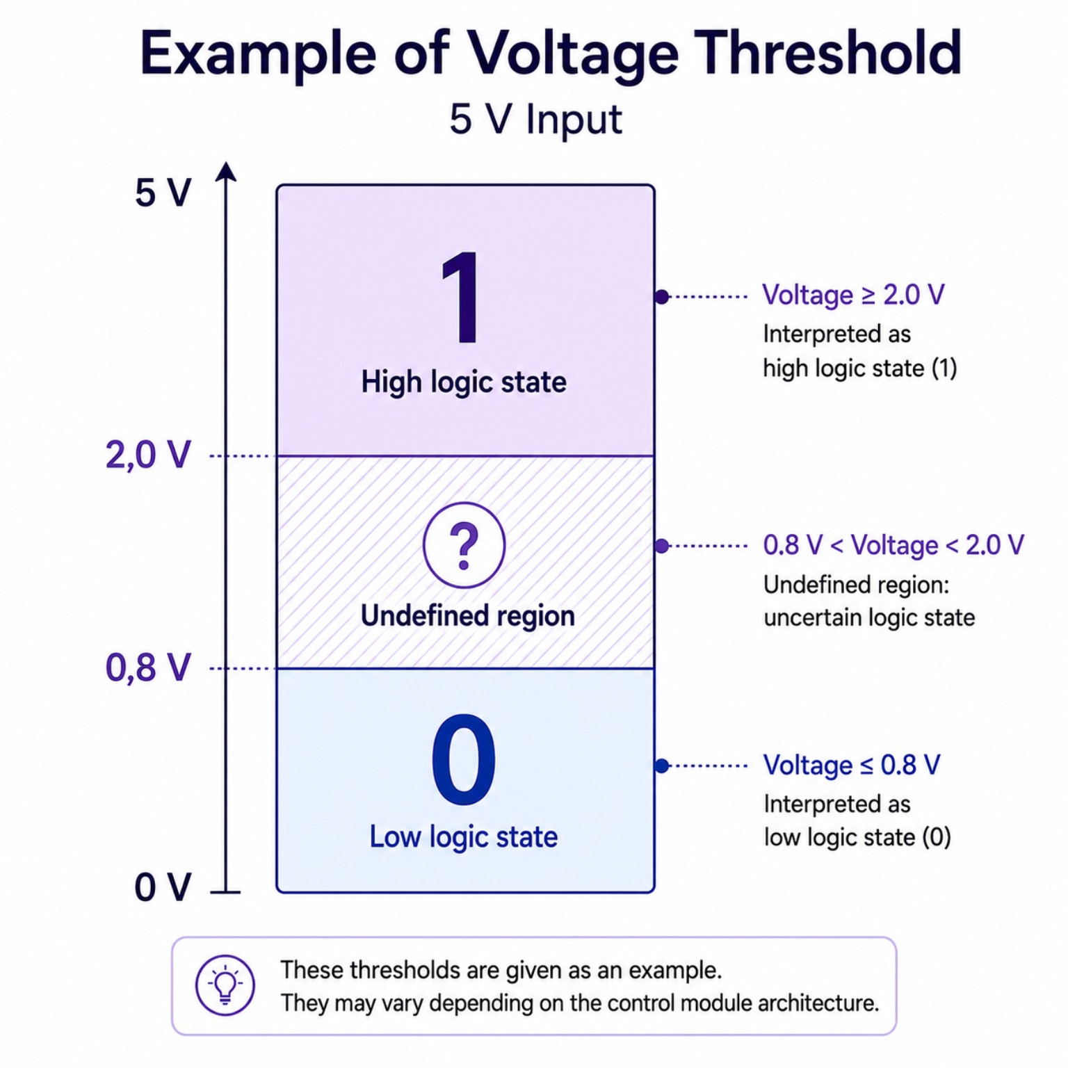
A control-unit input does not necessarily require exactly 0 V to recognize a low level or exactly 5 V to recognize a high level.
The decision is based on internal thresholds.
Consider, purely as an example, an input operating over a 5 V range:
0 to 0.8 V: logic low → 0
0.8 to 2 V: undefined region
2 to 5 V: logic high → 1
These values are not universal thresholds. The actual thresholds depend on the design of the input circuit.
Thus, 0.1 V, 0.3 V or 0.6 V can all be interpreted as the same logic-low state. In the same way, different voltages that are sufficiently high can be recognized as the same logic-high state.
A fault, however, does not always cause a clean open circuit or a signal permanently stuck at 0 V or at its high voltage.
A deteriorated contact, a resistive connection or a wiring fault can produce an intermediate or unstable voltage. Depending on the input thresholds, the control unit may then fail to recognize the state change, recognize it intermittently or switch between the two states.
Testing the state change
Testing can begin by observing the corresponding parameter in the control unit.
We successively produce both states of the device and observe how the parameter responds.
For example:
- Door open → parameter ‘open’
- Door closed → parameter ‘closed’
If the parameter changes in accordance with the applied condition, the control unit is receiving and recognizing the state change.
If it remains fixed or changes inconsistently, we can return to the electrical circuit.
Using the wiring diagram, we then check the voltage on the signal line in both states.
Is the change present at the output of the contact switch or device concerned?
If it is, do we find the same change at the control-unit input?
This progression allows us to determine where the information stops changing correctly.
A correct voltage at the device but an incorrect voltage at the control-unit input directs the investigation towards the circuit connecting them. If the voltage reaches the control-unit input correctly while the corresponding parameter does not change, diagnosis must continue on the control-unit side, notably by checking its power supplies and grounds, before considering an internal fault.
The measurement location is therefore essential: observing a voltage change at one point in the circuit does not prove that it reaches the input that must interpret it correctly.
Conclusion
Binary information may seem simple because it has only two states. Diagnosing it nevertheless requires us to distinguish the state of the device, the electrical level transmitted and the state recognized by the control unit.
Following this chain allows us to understand where the information stops being transmitted or interpreted correctly.