The control unit does not directly see that a wire is open or that a sensor has been disconnected.
It can only observe the electrical behaviour of the line, particularly the voltage present at its input.
A pull-up or pull-down is one common way of providing this bias, particularly on sensor lines. The exact way in which the bias is generated depends on the input-stage architecture.
With pull-up biasing, the line is drawn towards a positive voltage. With pull-down biasing, it is drawn towards ground.
As long as the sensor is acting normally on the line, its operation helps determine the voltage present at the control-unit input. If that connection disappears, for example because the sensor is disconnected or its signal wire is open, the sensor’s influence also disappears.
The bias resistor can then draw the input towards its pull-up or pull-down level instead of allowing the line to float.
This behaviour enables the control unit to turn certain electrical faults into detectable states.
Analog Sensor: Moving Outside the Normal Range
Consider an analog sensor supplied with 5 V.
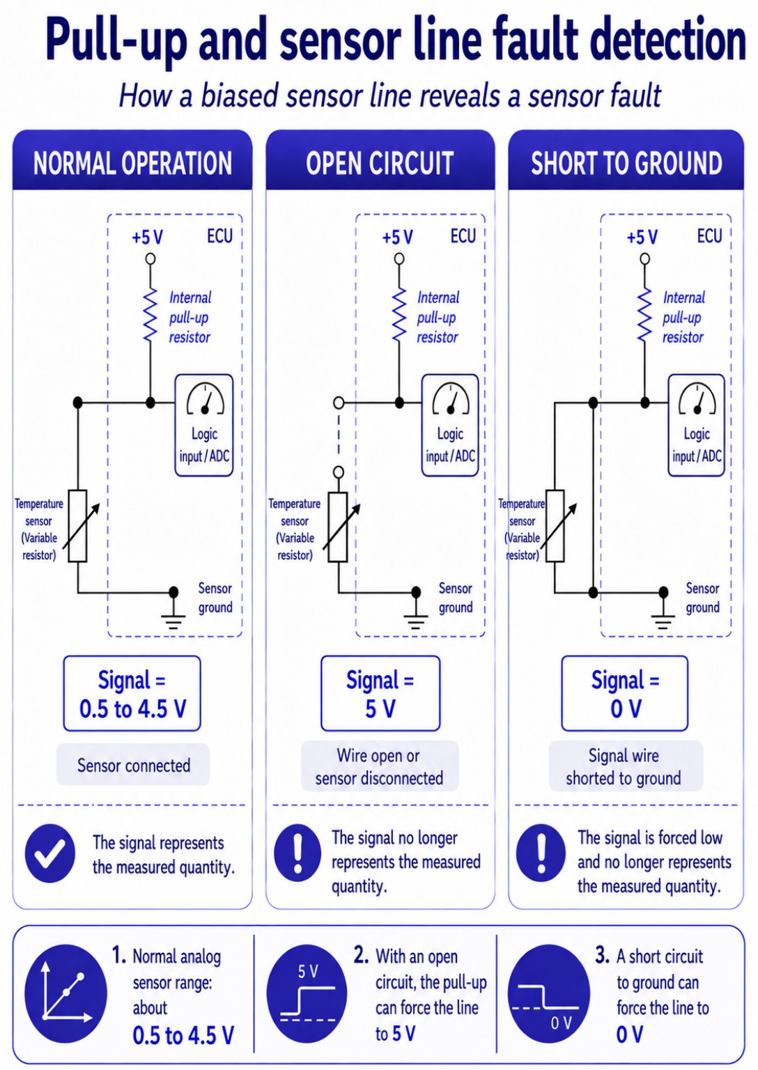
In normal operation, its signal generally varies within a range of approximately 0.5 V to 4.5 V.
On automotive analog sensor signal lines, biasing towards 5 V is very common. The pull-up voltage then often corresponds to the sensor supply voltage, although this is not a universal rule.
Pull-Up Biasing
If the sensor is disconnected or its signal wire is open, the pull-up bias can draw the line towards 5 V.
A short circuit to a positive voltage can also drive the line to a high level.
With pull-up biasing, an abnormally high voltage can therefore be caused either by an open circuit or by a short circuit to positive.
Conversely, a short circuit to ground draws the line towards 0 V and produces an abnormally low signal.
Pull-Down Biasing
With pull-down biasing, the behaviour of an open circuit is reversed.
If the sensor is disconnected or its signal wire is open, the pull-down bias draws the line towards 0 V. A short circuit to ground can also hold the line at this level.
With pull-down biasing, an abnormally low voltage can therefore be caused either by an open circuit or by a short circuit to ground.
Conversely, a short circuit to a positive voltage drives the line to an abnormally high level.
In these different cases, the voltage moves outside the normal signal range. The control unit can then detect that the value it is receiving is no longer consistent with the sensor’s expected operation.
The voltage being read no longer represents the measured quantity: it is now determined by the fault and by the electrical architecture of the line.
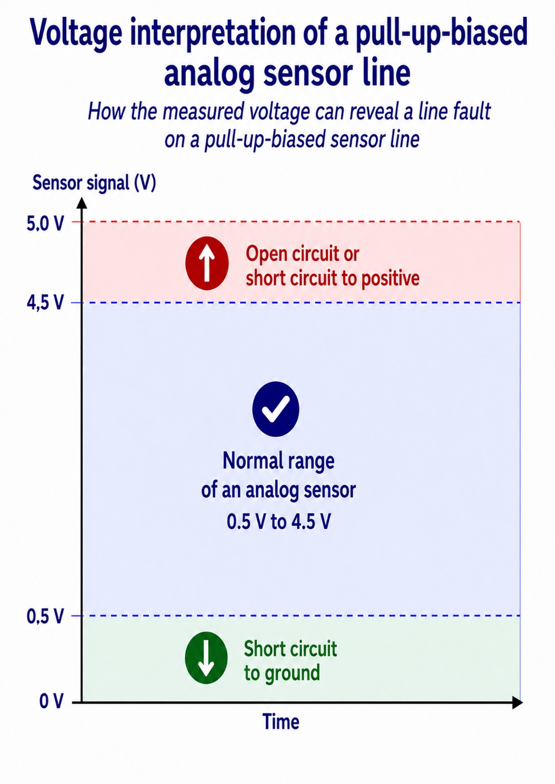
A ‘circuit high’ or ‘circuit low’ DTC therefore primarily describes the electrical state observed by the control unit. On its own, it cannot identify the physical nature of the fault.
Digital Sensor: Loss of Switching
The same principle also applies to digital sensor lines when they are biased by the control unit.
A digital signal normally switches between a low level and a high level.
On a pull-up-biased line, the high level may be imposed by the control unit and may differ from the sensor supply voltage. It is therefore not necessarily 5 V and may, for example, be around 4.2 V — or another value — depending on the circuit architecture.
If the sensor is disconnected or the line is open, the line may remain fixed at the pull-up voltage instead of switching. With pull-down biasing, it may instead remain fixed at the low level.
Depending on the monitoring strategy used, the control unit may use this fixed electrical level, the absence of switching or other characteristics of the expected signal to detect the fault.
The Principle Can Also Apply to Actuators
Biasing can also be used on certain actuator lines to make an open circuit or a disconnected component electrically observable.
Depending on the output-stage architecture, this diagnostic bias may be continuous or applied only briefly, for example in the form of diagnostic pulses. The control unit may then evaluate the resulting voltage or current to determine the electrical state of the circuit.
The control unit therefore does not directly ‘see’ the open circuit or the disconnected component. It detects the electrical effect that the condition produces in the circuit.
Conclusion
Biasing is therefore not used only to give a line a defined state. It can also make certain electrical faults observable by the control unit.
An open circuit, a disconnected component or a short circuit changes the behaviour of the line. The observed voltage or switching activity may then no longer match what the control unit expects.
Biasing makes the fault detectable; on its own, it does not necessarily identify the exact cause.
The same bias voltage can then be used as a reference when locating the fault during diagnosis, a principle developed in the article: How to Use Line Biasing in Diagnosis.