In the articles devoted to this subject, we have discussed the principle of pull-up and pull-down resistors, a particular and historically widespread method of biasing an electrical line. We have also seen how this biasing can allow the control unit to make certain line faults electrically observable and therefore detect them.
But biasing is not only useful to the control unit for detecting a fault.
It can also become a reference for the technician.
When biasing is used to make the electrical state of a line observable to the control unit, we can also use it to guide diagnosis.
Not every line is necessarily biased. But when a control unit is able to diagnose an open circuit or a short circuit on the line, we can expect the circuit to include a means of making those states electrically detectable.
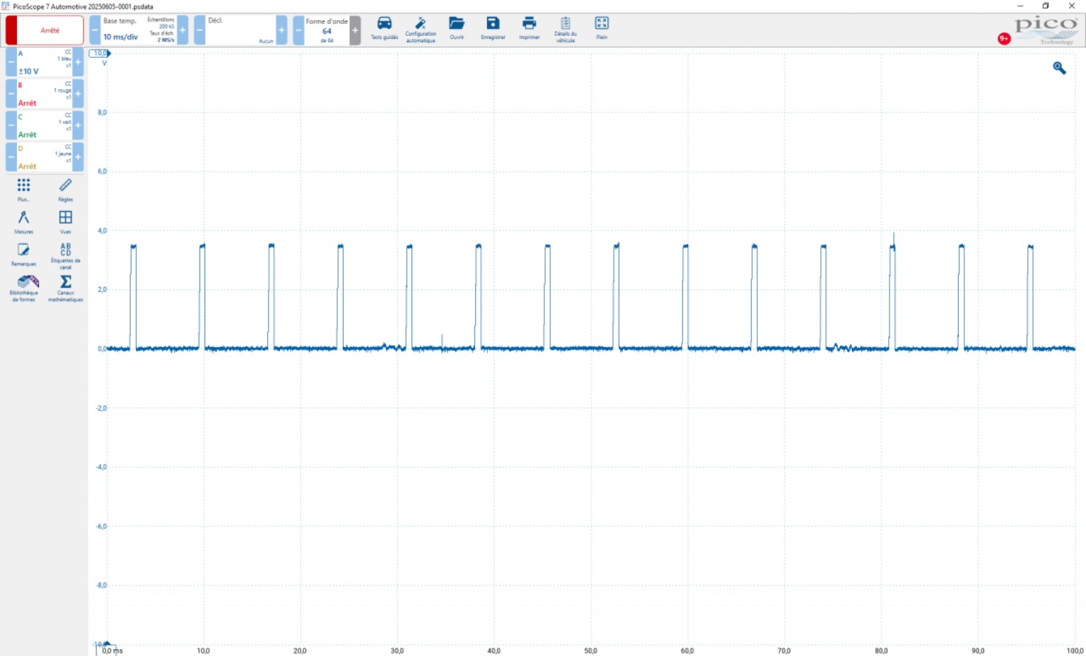
This bias can then be observed with an oscilloscope as a voltage on the line, including 0 V. This voltage may be constant or vary over time depending on circuit operation.
DTCs indicating an open circuit, a short circuit, circuit high or circuit low are therefore useful clues when looking for this behaviour.
How this bias is used depends on the expected value and can be difficult when the steady bias corresponds to 0 V or a supply voltage (5 V, battery voltage, etc.), because it may then be difficult for the technician to distinguish it from a short circuit to ground or positive.
By contrast, when it produces a characteristic voltage on the line with the component disconnected, whether constant or varying, distinct from 0 V or the circuit’s supply voltages, it can become a particularly useful diagnostic reference.
Isolating the Component to Observe the Line
When a component is connected, the voltage present on the line results from the interaction between the component, the control-unit circuit, the wiring harness and the connections linking them.
By disconnecting the component, we remove its influence from the line.
With the ignition on and the circuit activated, we can then observe with an oscilloscope the voltage present at the relevant terminal on the harness side.
If we find the characteristic bias voltage again, we have an electrical reference that we can look for at different points in the circuit.
Following the Bias Through the Circuit
If this voltage is present at the component connector, we know that the bias coming from the control-unit side reaches this point in the circuit.
The line is therefore not clearly open and is not being held at another potential by a short circuit at the time of the test.
If this voltage is not present, the check can be repeated directly at the control-unit output.
If it is present on the control-unit side but absent on the component side, the fault is probably located in the wiring harness or the connections.
If it is absent from the control unit itself, we must check the circuit activation conditions, the supplies, the grounds and the relevant stage inside the control unit.
Finding the same characteristic bias at the connector can therefore rule out a clear open circuit or a hard short circuit. However, this does not rule out a parasitic resistance or a poor contact that would appear only when the circuit is loaded.
Conclusion
When it produces a characteristic voltage, biasing can become a reference that we follow between the control unit and the component to progressively locate a fault.
It does not constitute a diagnosis on its own. It provides additional information about the state of the line and helps us determine the next checks to perform.