In many automotive circuits, a control-unit input is not left electrically floating when nothing is driving it.
If it were, the line could float, pick up interference or assume an inconsistent voltage.
To prevent this, the control unit can impose a default state through a bias resistor.
This is the principle of pull-up and pull-down:
- with a pull-up, the resistor connects the line to a positive voltage, often 5 V;
- with a pull-down, it connects the line to ground.
The line therefore has a defined electrical state even when the switch is open.
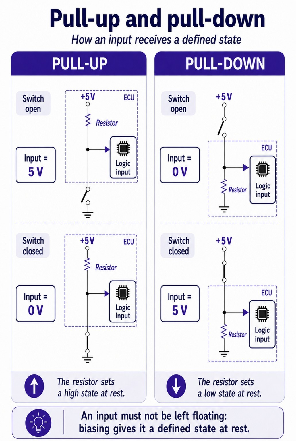
Pull-Up: A High State at Rest
Consider a common arrangement: a switch connected to ground and a pull-up resistor inside the control unit.
Switch open → the line rises towards 5 V.
No current flows to ground through the switch because it is open. The pull-up resistor therefore holds the input at a logic-high level.
Switch closed → the line falls towards 0 V.
When the switch closes, it connects the line to ground. The control-unit input is then brought to ground potential and changes from logic high to logic low.
The pull-up resistor now has a potential difference across it. Current flows through it and it dissipates a small amount of power.
This resistor plays an essential role here: it limits the current when the switch connects the line to ground.
Closing the switch therefore does not create an accidental short circuit between the supply and ground. The resistor is part of the circuit and deliberately limits the current.
Grounding the line is the normal operation of the circuit and allows the input to change state.
Pull-Down: A Low State at Rest
The principle is reversed with a pull-down.
This time, the resistor connects the line to ground.
Switch open → the line remains close to 0 V.
The pull-down resistor holds the input at a logic-low level.
Switch closed, connecting the line to a positive voltage → the line voltage rises.
The input then changes from logic low to logic high.
In both cases, the principle remains the same: a resistor defines the state of the line when the device controlling it is open.
Conclusion
Pull-up and pull-down resistors keep a line at a defined electrical level when it is not being driven, while allowing the device to switch it to the opposite state.
This biasing explains, in particular, why a voltage may be present on a line while the switch is open, or why grounding the line may be normal circuit operation.
Biasing can also allow the control unit to detect certain line faults, a principle developed in the article: Pull-Up and Pull-Down: How Biasing Reveals a Line Fault.