1. Why monitor the high-voltage network?
In an electric or hybrid vehicle equipped with a high-voltage system, the traction battery is connected to an electrical network that includes several power components: an electric motor, an inverter, an on-board charger where fitted, a DC/DC converter, an air-conditioning compressor and, in some cases, an electric heater.
Depending on the vehicle, the system voltage can reach several hundred volts.
For a given power, using a higher voltage reduces the current. However, these voltage levels require appropriate monitoring and protection devices.
The risks are not limited to direct contact with a live conductor. An insulation fault, overcurrent, excessive heating or component failure can also compromise system safety.
To prevent these situations, vehicles use several complementary monitoring functions.
Some monitor the battery's electrical condition, while others monitor network insulation, high-voltage connections or the operation of disconnect devices.
It is important to distinguish monitoring from protection: detecting a fault does not necessarily mean immediately interrupting the high-voltage supply.
The response depends in particular on the nature and severity of the fault and the vehicle's operating state.
2. What does the vehicle monitor?
Battery voltage and current
The traction battery consists of many electrochemical cells connected in series and, depending on its design, in parallel.
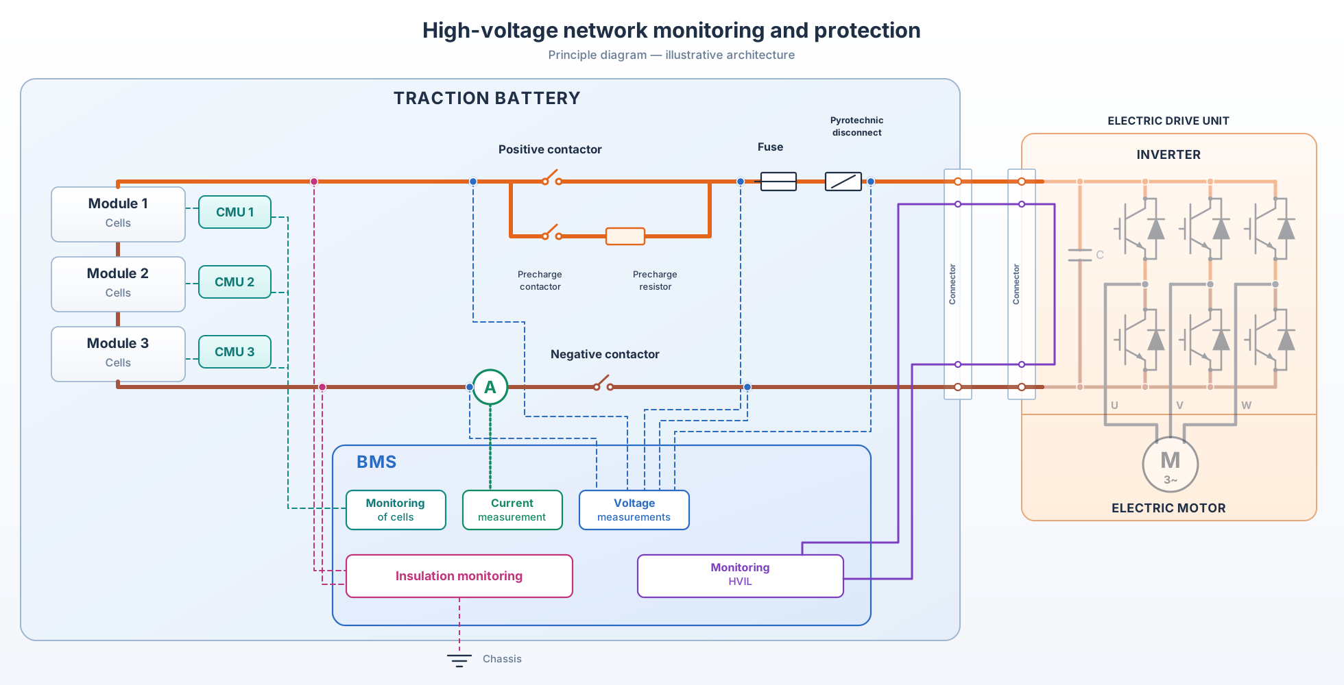
The battery management system, generally known as the BMS, supervises the voltages of individual cells or cell groups, as well as the charging and discharging current.
Depending on the architecture, electronic cell-monitoring units, often referred to as CMUs (Cell Monitoring Units), measure individual cell voltages and collect temperature information. They transmit these data to the BMS, which uses them to monitor the battery's condition and adjust its operation.
Charging and discharging current is measured by a sensor in the battery's power circuit, generally on one of its main connections. Depending on the technology used, this measurement may rely on a resistive shunt or a magnetic sensor, such as a Hall-effect sensor.
This information helps detect, in particular:
- a cell voltage that is too high or too low;
- an imbalance between cells;
- a current exceeding the permitted limits.
It also contributes to estimating the battery's state of charge (SOC) and state of health (SOH).
Monitoring individual voltages is particularly important: an apparently correct total voltage can conceal a fault in a cell or cell group.
Temperature
Battery cells have operating temperature ranges defined by their design.
Temperatures that are too low can limit their charging and discharging capabilities, while excessive temperatures accelerate ageing and can present safety risks.
Sensors distributed throughout the battery allow the management system to monitor temperatures and, depending on the architecture, differences between them.
The vehicle can then adjust cooling, activate battery heating, limit current or interrupt certain operations.
Electrical insulation
A vehicle's high-voltage network is normally electrically isolated from the chassis.
Unlike many automotive low-voltage circuits, the chassis therefore does not serve as the normal current return conductor.
This separation contributes to personal safety by limiting the risk of dangerous current flowing through the human body during simultaneous contact with a high-voltage conductor and the chassis.
Degraded insulation can create a leakage path between the high-voltage network and the chassis. Detecting it allows the vehicle to apply a protection strategy before the situation presents an increased risk.
Insulation monitoring is often associated with the battery management system (BMS), which may use information provided by a dedicated measurement circuit. Its coverage depends on the circuits actually connected to the measurement device.
Deterioration may trigger a warning, prevent energisation or lead to other protective measures, depending on the manufacturer's strategy.
High-voltage connections: the HVIL
The HVIL (High Voltage Interlock Loop) is a safety system intended to monitor whether certain connections and access devices in the high-voltage network are securely closed or locked.
It generally relies on a low-voltage electrical loop associated with the monitored connectors and devices.
In a conventional HVIL architecture, auxiliary interlock contacts are integrated into the monitored high-voltage connectors or associated with certain protection and isolation devices. Opening these contacts interrupts the continuity of the loop and allows the system to detect a fault.
When a fault is detected, the vehicle may prevent energisation or apply an appropriate protection strategy.
High-voltage contactors and precharge
The traction battery generally contains contactors that electrically connect the battery to, or separate it from, the vehicle's high-voltage network.
Their operation is monitored to check that opening and closing commands produce the expected effects.
Depending on the architecture, control units may use voltages measured on either side of the contactors or information from auxiliary position-feedback contacts.
These checks can help detect, in particular, a contactor that does not close or remains welded in the closed position.
In many architectures, closing the contactors is also associated with a precharge phase.
This operation gradually charges the capacitors in the high-voltage network, particularly those in the inverter, to limit inrush current and the electrical stresses imposed on components when the battery is connected.
Monitoring how the voltage changes allows the system to verify the progress of this phase before authorising the main connection.
3. How do monitoring systems contribute to high-voltage safety?
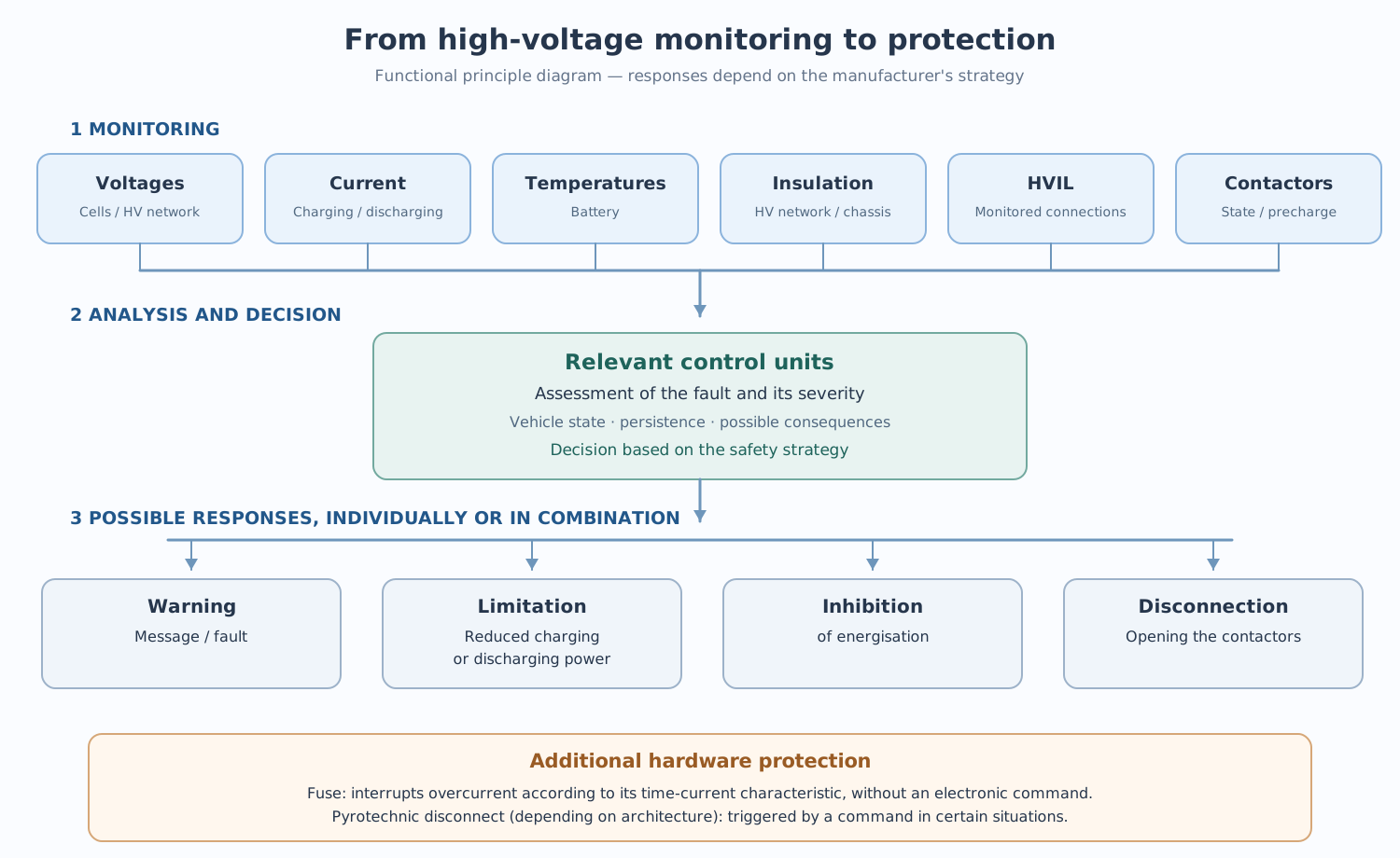
The information collected by the various monitoring systems is used by the relevant control units, which can exchange data and coordinate their actions.
The battery management system (BMS) plays a central role in monitoring the cells and controlling the battery contactors. However, the organisation of safety functions varies between manufacturers.
When energisation is requested, several conditions may be checked: battery condition, absence of an insulation fault that prevents energisation, correct interlock status and availability of the connection devices.
When the necessary conditions are met, the system can authorise precharge followed by closing the main contactors.
Monitoring continues while the vehicle is operating to detect faults that may require high-voltage operation to be adjusted or interrupted.
Network safety therefore relies on several complementary checks whose results contribute to the decisions made by the vehicle's control units.
4. How does the vehicle respond to a high-voltage fault?
When a monitoring function detects abnormal behaviour, the relevant control unit may store a diagnostic trouble code and transmit the information to other control units.
The response depends on several parameters: fault type, severity, persistence, vehicle state and the possible consequences of interrupting the power supply.
Several levels of response are possible.
Warning
Some faults mainly result in a stored fault code and a message displayed to the driver.
Limiting operation
Some faults may cause the vehicle to reduce charging or discharging power. This can occur, for example, when the battery temperature is too high or a cell voltage approaches its limits.
These limits keep components within their permitted operating ranges and help prevent certain forms of deterioration. The vehicle may therefore continue to operate, but with reduced performance.
Preventing energisation
When the safety conditions are not met, the system may refuse to close the high-voltage contactors.
This can occur, in particular, with certain interlock, insulation or contactor-control faults.
Disconnecting the high-voltage network
In certain situations, the system may command the contactors to open to separate the battery from the rest of the network.
This disconnection may be commanded following the detection of a collision, for example.
Other protection devices may also intervene. A fuse protects the circuit against overcurrent by interrupting the current according to its time-current characteristic, without requiring an electronic command. Some architectures also include pyrotechnic disconnect devices that can physically interrupt an electrical connection when triggered.
Disconnection does not mean absence of voltage
Opening the contactors does not guarantee the absence of voltage throughout the vehicle. The battery retains its internal voltage, and certain components may retain residual voltage, particularly in their capacitors.
Work on the high-voltage system must follow the manufacturer's safety procedures. Where the work requires a formal safe-isolation procedure, this includes verifying the absence of voltage in accordance with the applicable requirements.
Conclusion
In electric and hybrid vehicles, high-voltage safety relies on several complementary monitoring systems combined with protection strategies suited to the faults detected.
These devices do not all perform the same functions: some monitor electrical or thermal conditions, while others allow the high-voltage supply to be controlled or interrupted.
Understanding their respective roles and interactions is an essential first step towards measurement methods and diagnostics for high-voltage systems.