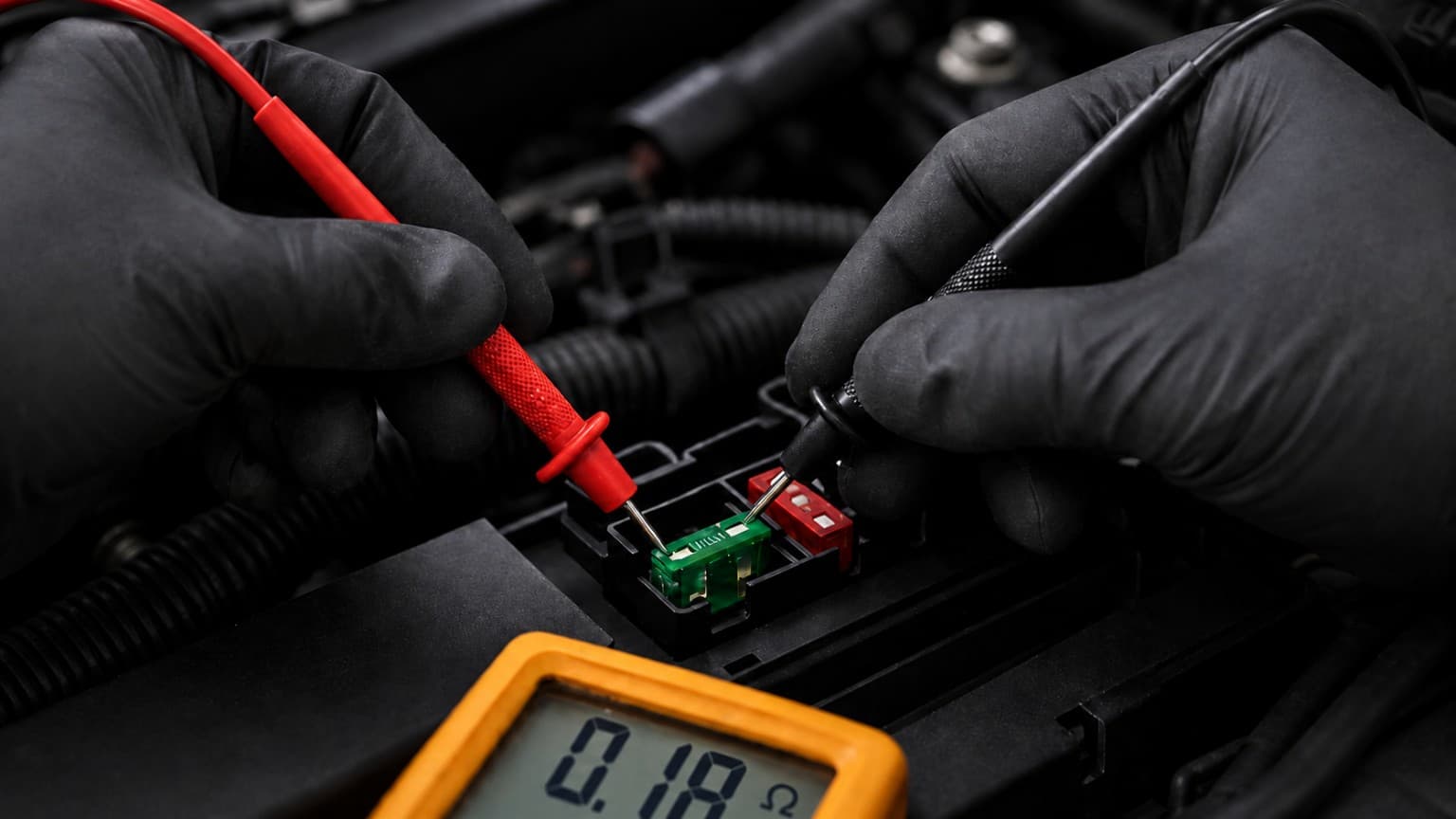
The multimeter beeps. The ohmmeter displays a very low resistance. The wire is therefore declared to be in good condition.
Yet once the load is connected, the circuit no longer operates and its supply voltage collapses.
Were the measurements wrong? No. Their interpretation was.
1. A beep does not mean the wire is in good condition
Continuity mode only detects the existence of an electrical path between the two multimeter probes.
Its activation threshold varies from one instrument to another. Some multimeters continue to beep with several tens of ohms present, sometimes up to 30 or 50 Ω.
Yet this level of resistance would be completely incompatible with the operation of many automotive circuits.
A corroded wire, a cracked fuse, a damaged crimp or a deteriorated connector may therefore trigger the continuity buzzer while still being unable to carry the required current.
Continuity mode remains useful for certain quick checks on a de-energised circuit, such as locating a complete open circuit, identifying a conductor or checking whether a contact is open or closed. However, it cannot validate the circuit’s actual ability to carry current.
The continuity buzzer is a contact detector, not a functional continuity test.
2. Even a very low resistance does not validate the circuit
An ohmmeter provides additional information by displaying a resistance value. However, it also performs its measurement using a very low current, typically only a few milliamps.
An abnormally high value may reveal deterioration in the electrical path. But a low value, even 0.1 Ω, does not prove that the path can correctly carry the required current.
This is the key point: a low resistance measured with no load does not validate the circuit’s ability to carry its actual operating current.
The effect of this resistance depends directly on the current drawn by the circuit. A parasitic resistance of 0.1 Ω causes a voltage drop of only 10 mV at 100 mA, but a drop of 1 V at 10 A.
The same resistance value may therefore have almost no effect in a lightly loaded circuit while making a power circuit unusable.
Accurately measuring such low resistance values with a conventional multimeter is also difficult. The test leads, probe tips and quality of the contact may already account for a significant proportion of the displayed value.
An ohmmeter can reveal a poor electrical path. But a low reading is not enough to conclude that the path is sound.
3. The fault only becomes apparent under load
Whenever current flows through a resistance, a voltage develops across it.
In a conductor that is in good condition, resistance is very low, so the voltage drop remains small. In a corroded connection or partially damaged wire, parasitic resistance produces a voltage drop that increases with current.
When the circuit is not under load, current is almost zero. The voltage drop is therefore also almost zero, and the fault may remain hidden.
This is why measuring battery voltage at a disconnected supply connector does not validate the circuit. A multimeter draws so little current that even a severely deteriorated path may still provide an apparently normal voltage reading.
When the load is connected, the required current flows through the parasitic resistance. Part of the voltage is then lost across the wiring, connector, fuse or defective crimp. The voltage actually available across the load may become insufficient.
The reliable method is therefore to operate the circuit under a representative load and measure the voltage drop across the electrical path being tested.
Instead of merely asking whether the wire is ‘continuous’, we directly observe how much voltage it loses while carrying the required current.
4. Example: 12.3 V with no load, 7.1 V under load
An ECU is no longer communicating.
With the connector disconnected, the voltage measured between its supply wire and the battery negative terminal is 12.3 V. The voltage appears correct.
The ECU is then reconnected. When it attempts to operate, the voltage available at its supply input falls to 7.1 V.
A voltage-drop measurement between the battery positive terminal and the ECU supply then indicates 5.2 V.
The positive supply path therefore contains significant parasitic resistance.
By progressively moving the test probes along the circuit, the entire voltage drop is eventually found across the fuse holder.
With no load, the current drawn by the multimeter was too low to make the fault visible. Under the ECU’s load, the voltage collapsed across the deteriorated fuse holder.
The wire had continuity. The fuse was not open. Voltage was present with the connector disconnected. Yet the circuit was unable to operate.
Conclusion
A circuit may appear perfect at rest and then collapse as soon as it is placed under real operating conditions.
Continuity mode only confirms the existence of an electrical path. An ohmmeter may reveal obvious deterioration, but a low resistance measured with no load does not guarantee that the circuit can carry its operating current.
Reliable validation of an electrical path requires measuring its voltage drop under a representative load and under actual operating conditions.